Introduction to Geotextiles | Testing of geotextile material
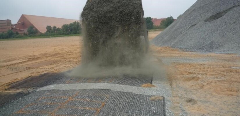
Geosynthetic materials like Geotextiles, Geogrids, Geonets, Geocell, and Geomembranes are used in various civil engineering activities especially in highway engineering to facilitate construction, ensure better performance of the structure and reduce maintenance. To know the performance of these products, performance evaluation is to be done & to meet the requirements, quality has to be maintained.
Geosynthetics are polymeric materials that are used in below-grade construction in a broad and ever-increasing range of applications. The majority of the applications generally fall into the areas of geotechnical, environmental, transportation, and hydraulic engineering.
Geotextiles are typically woven or non-woven fabrics made from polypropylene (PP) or polyester (PET) fibers, filaments, or yarns using conventional textile manufacturing facilities. There is considerable variation in the final product, with commercial geotextiles typically ranging in mass per unit area from 135 to 1000 g m-2, and in strength from 9 to 180 kN m -1 for filtration or separation applications.
Geotextiles with a higher mass per unit area and strength are also available for severe installation conditions and reinforcement applications.
Other polymers, such as high-density polyethylene (HDPE), polyamide (PA), and polyvinyl alcohol (PV A) are also used, but to a lesser extent than PP and PET. Due to the inherent variability of different geotextiles, product-specific properties are always needed.
Functions of Geotextiles
Geotextiles are commonly used to improve soils over which roads, embankments, pipelines, and earth retaining structures are built. There are several types of geotextile material, including open-mesh, warp-knitted, and closed fabric or non-woven textiles.
Different geotextile materials are specified for various characteristics, such as separation, filtration, drainage, reinforcement, sealing, and protection.
Geotextile separation
When a geotextile is installed between two different soil materials, the function of separation plays an important role. In this case, the geotextile will separate dissimilar materials so the required soil characteristics can be obtained.
The main purpose of this type of geotextile is that when water gets into the soil strata, the geotextile will prevent soils from mixing. For example, in road construction, you might want to keep fine sub-grade aggregate separate from the coarse aggregates of the bottom layer.
By doing this, the drainage characteristics will be kept intact, preventing the fine aggregate from filling the voids between the larger aggregate. These types of geotextiles have special thickness and permeability characteristics to prevent soil contamination and allow water to flow through without damaging the strength and structural capacity of the road.
Geotextile Filtration
Filtration geotextile characteristics are used to allow for water to move in both directions. These types of geotextiles can be woven or non-woven and are used to prevent fine aggregates from moving between soil layers.
Depending on the porosity and permeability of the material, geotextiles also can promote the lateral flow of drainage water, dissipating the kinetic energy of the capillary rise of groundwater. Geotextiles can be used in both vertical and horizontal applications, helping to solve drainage problems around homes and along roads and curbs.
Reinforcement
When a geotextile is used to improve soil characteristics, its design is based on a few key factors:
- Friction or movement restraint
- Support of loads
- Changes in bearing failure plane
This is comparable to the function of rebar in concrete. Geotextiles are used on embankments and roads being built over very poorly graded soils, allowing for steeper embankments. For such applications, it is always recommended to have design parameters provided by a geotechnical engineer.
Drainage
The next function of Geotextiles is drainage which is to flow water vertically and horizontally directly from the ground. Vertical water flow has the aim to drain the water that is in the subsoil, it is hoped that there will be effects such as consolidation.
Whereas for irrigation water with a horizontal system, the aim is to flow water from the ground surface to the final drainage channel. The application of drainage is used in places such as sports stadiums, golf courses, airports, embankments to beach reclamation.
Geotextiles As Geosynthetics
Geotextile is a type of geosynthetics. Now, geosynthetics can be defined as the membranes used in contact with or within the soil.
So, let’s look at other types of geosynthetics:
- Geomembranes
- Geogrids
- Geonets
- Geocomposite
1. Geomembranes
Geomembranes are Polymeric sheets used as barriers for the containment of liquids, gases, or solids. Geomembranes are generally synthetic or bituminous manufactured sheets acting as resistant material. They are mainly used as a liquid-vapor barrier in landfills and waste containment facilities. The reason behind this application is its extremely low permeability.
They can be classified as:
- Calendered Geomembranes: A molten viscous formulation of Polypropylene or Polyvinyl Chloride is passed and flattened between counter-rotating rollers.
- Extruded Geomembranes: Molten polymer chips are forced through a die with the help of a screw extruder. They are followed by a conveyor belt and finally pulled by a nip roller above the die.
| Test | Test Method |
| Accelerated Weathering Testing (QUV) | ASTM G 53 |
| Bonded Shear Strength | ASTM D 4437 |
| Breaking Strength | ASTM D 882 |
| Brittleness Temperature (°C) | ASTM D 746 |
| Brittleness Temperature (°C) | ASTM D 1790 |
| Carbon Black Content (%) | ASTM D 1603 |
| Carbon Black Dispersion | ASTM D 3015 |
| Chemical Resistance of Geosynthetics to Liquids | ASTM D 5322 |
| Coated Fabrics @ Low- Temperature Bend | ASTM D 2136e1 |
| Coefficient of Friction by Direct Shear | ASTM D 5321 |
| Density (g/cm3) | ASTM D 792(A) |
| Deterioration Resistance to Surface Ozone | ASTM D 1149 |
| Environmental Stress Crack Resistance | ASTM D 1693 |
| Full Series Tensile (MD) | ASTM D 638/NSF Mod. |
| Full Series Tensile (CD) | ASTM D 638/NSF Mod. |
| Hydrostatic Resistance | ASTM D 751 |
| Linear Dimension Change @ Elevated Temperature | ASTM D 1204 |
| Melt Index (g/10 min) | ASTM D 1238 |
| Peel & Shear Strength (PVC) | ASTM D 3083/NSF 54 Mod. |
| Peel Strength, PE (single-trac welds) | ASTM D 4437/NSF Mod. |
| Peel Strength, PE (double-trac welds) | ASTM D 4437/NSF mod. |
| Puncture Resistance | FTMS 101C, Method 2065 |
| Shore Hardness | ASTM D 2240 |
| Wide Strip Tensile | ASTM D 4885 |
| Tear Resistance (MD) | ASTM D 1004 |
| Tear Resistance (CD.) | ASTM D 1004 |
| Thickness | ASTM D 1593 |
| Tongue Tear Strength | ASTM D 751/NSF Mod. |
| Volatile Loss | ASTM D 1203 |
2. Geogrids
Geogrids are grid-like sets of interconnected ribs with large apertures primarily used for soil reinforcement. These are mainly manufactured sheets (single or multi-layer) having a regular network of integrally associated parts. High-density polyethylene or polypropylene is extruded and stretched, or polyester yarns are weaved or knitted and finally coated to make geogrids.
As they have larger openings (apertures), they are suitable for reinforcement materials. Five types of geogrids are available.
- Unidirectional
- Bi-directional
- Extruded
- Woven
- Bonded
The following table lists testing offered for Geonet materials.
| Test | Test Method |
| Density (g/cm3) | ASTM D 792(A) |
| Node Strength | GRI GG. |
| Rib Strength | GRI GG. |
| Wide Width Tensile | ASTM D 4595 |
3. Geonets
Geonets are net-like sets of integrally joined overlapping ribs used for in-plane drainage mainly made from polyethylene. A matrix or net is formed when the molten polymer is extruded through slits in counter-rotating dies. Mainly used in the drainage system as they do not have sufficient strength.
Geonet testing provides information on the capabilities of Geonet materials.
| Test | Test Method |
| CBR Puncture Resistance | GRI GS. |
| Compression Behavior | GRI GN. |
| Density (g/cm3) | ASTM D 792(A) |
| Moisture Content % | ASTM D 4643 |
| Moisture Content | CRT Method |
| Mass per Unit Area | ASTM D 3776 |
| Strip Tensile Strength (MD) | ASTM D 5035 |
| Strip Tensile Strength (CD.) | ASTM D 5035 |
| Transmissivity (single load) | ASTM D 4716 |
| Transmissivity (multi-load + gradient) | ASTM D 4716 |
| Transmissivity (common loads per spec.) | ASTM D 4716 |
| Ply Adhesion | ASTM F 904 |
4. Geocomposites
Geocomposites are made by combining different geosynthetics materials or by combining geosynthetic materials with non-synthetic materials, such as bentonite clay, to address specific applications in the field in an optimal manner with minimum cost.
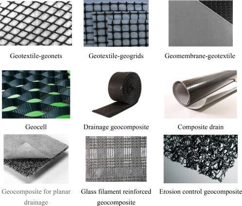
Geocomposite materials include geotextile-geonets, geotextile-geogrids, geotextile-geomembranes, geomembrane-geonets, geosynthetics clay liner (GCL), geotextile-polymeric cores, or three-dimensional polymeric cell structures. Various forms of geocomposite materials.
Geocomposites are used for basic functions of roadways such as separation, drainage, filtration, and reinforcement. Geocomposites can be used to increase the strength and stability of underlying soil in a roadway. Geocomposites are used under the railway tracks to provide stabilization and reinforcement.
In-plane drainage using geosynthetics is usually designed with either geonets (usually in combination with a geotextile) or with a geocomposite, a class of geosynthetics often designed principally for in-plane drainage.
These hybrid geosynthetics are made by combining different types of geosynthetic components and serve the purpose of providing both filtration and drainage.
Geocomposites are typically combinations of a drainage (and sometimes barrier) material with a geotextile filter to prevent soil migration into the drainage system.
Geosynthetics used for drainage include perforated plastic pipes (or “geopipes”), geonets (ribbed materials intended to convey in-plane flow), and corrugated geomembranes (which can provide substantial in-plane flow capacity as well as a hydraulic barrier).
Geonets are typically formed by two biplanar sets of relatively thick, parallel, polymeric (usual polyethylene) ribs bonded in such a way that the two planes of strands intersect at a constant acute angle, forming a diamond-shaped pattern (Figure 8.5). The configuration of the nets forms a network with large porosity that enables relatively large in-plane fluid (and/or gas) flows.
While they have considerable tensile strength, they are used exclusively for drainage applications. Their initial use was almost exclusively for environmental applications, such as hazardous, liquid, waste impoundment, or landfills to collect and drain leachate fluids, and for leak detection.
Geonets have also been shown to provide effective capillary breaks where moisture intrusion due to capillary rise is a concern.
They have now become more widely used for drainage behind retaining walls, in slopes, in hydraulic structures (e.g., dams and canals), in large horizontal areas (e.g., golf courses, athletic fields, and plaza decks), and as drainage blankets beneath surcharge fills and embankments.
In order to prevent soil intrusion into the voids, geonets are generally used in conjunction with geotextiles and/or geomembranes.
While traditional biaxial geonets were never really intended to support any tensile or shear load, newer triaxial versions of geonets have been designed to provide even greater flow with added load capacity in both compression and shear (Figure 8.7). The triplanar structure provides minimal geotextile intrusion and greater flow capacity through longitudinal channels.
Their higher rigidity, tensile strength, and compressive resistance make them suitable for application within roadway pavement systems, beneath highways and airfields, and beneath concrete building slabs.
| Property | Parameters |
| General properties | Material type and construction, polymer(s), Mass, Thickness, Roll dimensions, specific gravity, Absorption |
| Index properties | Strip tensile strength, gray strength, Creep resistance, Flexural strength, Cutting – trapezoidal tear strength, Shear modulus, Poisson’s ratio, Burst strength, Puncture resistance, Penetration, Flexibility (flexural strength) |
| Endurance properties | Abrasion resistance, UV stability, Biological resistance, Chemical resistance, Wet/dry stability, Temperature stability, Long-term durability |
| Performance – soil/fabric properties | Stress–strain, CreepFriction/adhesion, Dynamic and cycling loading, Soil retention, filtration |
| Hydraulic properties | Apparent opening size, Percent open area, Porosity, Permeability/permittivity, Soil retention ability, Clogging resistance, In-plane flow capacity |
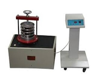
Testing of geotextile material carried out at ATIRA:
Determination of Mass per unit Area:
This standard explains a method to determine the mass per unit area of all-natural geotextile. The mass per unit area is calculated by weighing small square specimens of known dimensions.
Ten specimens of 100cm2 are cut from the material in such a way that they are representative of the material to be tested.
The area and weight of the specimens are determined to an accuracy of 0.5 and 0.1 % respectively.
The mass per unit area of each specimen is calculated using the equation p= (m X 106) /a
- Where p=mass/unit area in g/m2
- m=mass of the specimen in, g
- a=the area of the specimen in mm2
The average mass per unit area is calculated.
Determination of Thickness in geotextile testing:
This standard describes a method for the determination of the thickness of geotextiles at specified pressures.
The distances between a reference plate on which the specimen rests and a parallel presser-foot applying the given pressure to the specimen is defined as the thickness of the geotextile.
A thickness tester apparatus capable of exerting a pressure of 2kPa is used. The test specimen shall be cut from the material from positions evenly distributed over the full width and length of the sample.
The specimen is placed between the surfaces of the reference plate and the pressure foot of the thickness tester. The gauge reading is noted after 30 seconds. Remove the pressure and the specimen.
The procedure is repeated for at least ten specimens. The average of all the readings is reported as the thickness of the geotextile.
The thickness is expressed in mm to an accuracy of 1% for geotextiles thickness over 0.05mm and to the nearest 0.001mm for thickness not exceeding 0.05mm.
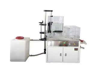
Permittivity:
Permittivity is the mechanism by which water moves through the fabric. The permittivity test measures the quantity of water which can pass through a geotextile perpendicular to the surface of the geotextile.
The permittivity may be measured either in a constant head or falling head test, although constant head testing is more common due to the high flow rates through geotextiles which make it is difficult to obtain readings of head change versus time in the falling head test. In the constant head test, ahead of 50 mm water is maintained on the geotextile throughout the test.
The quantity of flow is measured versus time. In the falling head test, a column of water is allowed to flow through the geotextile, and a reading of head changes versus time is taken. The flow rate of water through the geotextile needs to be slow enough to obtain accurate readings.
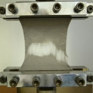
Grab Tensile Strength testing in geotextile
The grab test is a tensile test where the central part of the specimen’s width is tested to establish the “effective strength” of the fabric.
The effective strength is the strength of the material at a specific width when combined with the additional strength of adjacent material.
Test specimens are cut in both the machine direction and cross-machine direction but are expected to have their results calculated separately. Specimens are cut to 101.6 mm x 203.2 mm (4 in x 8 in), with attention to the direction of the fabric.
The specimen is loaded into the grips leaving a 75 mm (3 in) separation between the jaw faces. ASTM D4632 calls for jaw faces that are at least 25.4 mm x 50.8 mm (1 in x 2 in).
However, it allows for each grip to include one jaw face that is larger than the other (a modified grab test), which can be helpful in reducing the effects of specimen/jaw face alignment.
- Used for geotextile fabrics to determine the breaking load and elongation.
- This test method measures the ultimate strength and elongation.
- In this method, the specimen is clamped between two jaws. One is stationary and the other is movable jaw, the movable jaw moves gradually and the specimen starts to elongate. After a certain point the specimen breaks.
Trapezoid tearing strength
ASTM D4533; AS 3706.3
A specimen for the test is clamped in parallel jaws of a tensile testing machine, with a specified gauge length, along the nonparallel sides of a trapezoid shape that has been marked on a rectangular specimen with an initial cut.
The machine is operated at a constant speed so that the initial tear propagates across the specimen. Results are expressed in N.
Permeability (Geotextile testing):
Permittivity is the mechanism by which water moves through the fabric. The permittivity test measures the quantity of water which can pass through a geotextile perpendicular to the surface of the geotextile.
The permittivity may be measured either in a constant head or falling head test, although constant head testing is more common due to the high flow rates through geotextiles which make it is difficult to obtain readings of head change versus time in the falling head test.
In the constant head test, ahead of 50 mm water is maintained on the geotextile throughout the test.
The quantity of flow is measured versus time. In the falling head test, a column of water is allowed to flow through the geotextile, and a reading of head changes versus time is taken.
The flow rate of water through the geotextile needs to be slow enough to obtain accurate readings.
Determination of water flow/permeability (normal to the plane)
BS EN ISO 11058; BS 6906: Part 3
A constant head of water is applied to the specimen for a test that is clamped between circular flanges with a known exposed area. The water passing through the specimen is collected for a given period of time and flow rate/permeability is calculated.
Determination of water flow capacity in the plane (transmissivity)
BS EN ISO 12958; BS 6906: Part 7
The flow of water in the plane of the material is measured under varying normal compressive stresses, typical hydraulic gradients, and defined contact surfaces (used to model field conditions
Apparent Opening Size:
This test method indicates the apparent opening size in a geotextile, which reflects the approximate largest opening dimension available for soil to pass through.
A.O.S. is an important parameter in assessing a geotextile’s soil filtration capability. Spherical solid glass beads are dry sieved through a geotextile for a specified time and at a specified frequency of vibration.
The amount of beads retained by the geotextile sample is then measured. The test is carried out on a range of sizes of glass beads. The apparent opening size is the pore size at which 90% of the glass beads are retained on and within the fabric.
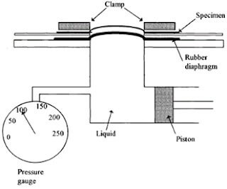
Burst Strength in Geotextile testing:
- It determines the strength or force required to rupture or burst the fabric.
- It is essential to maintain the gripping force to ensure reproducible test results.
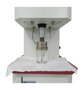
In this method the material is placed between two discs and the air pressure is applied from the bottom, bulb-shaped equipment is placed on top, and a vacuum is created. Thus after a certain point, the material bursts.
UV Resistance [ASTM D4355]
UV Resistance is a measure of the potential for the deterioration of tensile strength in the fabric due to exposure to ultraviolet light and water. It is typically expressed @ 500 hours exposure. For some products, such as ground cover, you will see it specified as high as 2,500 hours exposure.
Static CBR Puncture [ASTM D6241]
To eliminate the high degree of variability from the Mullen Burst (3786) and Pin Puncture (4833) test methods, Static (CBR) Puncture Strength (ASTM D 6241) was developed to replace them.
CBR stands for California Bearing Ratio, a soil strength test that was adapted for this geotextile test. CBR Puncture is an index of puncture resistance that measures the force required to push a flat-ended plunger through a geotextile.
A 150 mm geotextile sample is secured between two steel rings. Instead of an 8 mm diameter probe with a beveled edge (Pin Puncture 4833); this test utilizes a 50mm diameter, flat-ended probe (plunger) that is pushed slowly through the geotextile.
The relatively large size of the plunger provides a multidirectional force on the geotextile and simulates big stones pressed onto a geotextile laying a relatively soft sub-base.
If you are interested to get more information on geotextile testing, please write to marketing@atira.in